
This instructional will cowl the whole thing you want to comprehend to rise up and taking walks with Character LCDs. Not actually 16×2(1602) however any individual LCDs (as an instance, sixteen×4, 16×1, 20×4 and lots of others.) which can be based totally on parallel interface LCD controller chip from Hitachi called the HD44780. Because, the Arduino network has already advanced a library to handle HD44780 LCDs; so we’ll have them interfaced right away.
💬 Did you recognize?
An LCD is brief for Liquid Crystal Display. It is essentially a show unit which makes use of liquid crystals to offer a visible image.
When modern is completed to this unique shape of crystal, it turns opaque blocking the backlight that lives in the back of the show. As a end result that unique region will become dark compared to distinct. And that’s how characters are displayed at the display.
Hardware Overview
These LCDs are best for showing textual content/characters only, in the end the call ‘Character LCD’. The display has an LED backlight and might show 32 ASCII characters in two rows with sixteen characters on every row.


If you look carefully, you could simply see the little rectangles for every man or woman on the display and the pixels that make up a individual. Each of these rectangles is a grid of 5×8 pixels.
Although they display handiest text, they do are available in many sizes and sunglasses: as an example, sixteen×1, 16×4, 20×four, with white text on blue history, with black text on inexperienced and lots of extra.
The top statistics is that each one of those shows are ‘swappable’ – in case you assemble your project with one you may virtually unplug it and use every other size/shade LCD of your choice. Your code may additionally moreover need to alter to the bigger size but at least the wiring is the identical!
16×2 Character LCD Pinout
Before diving into hookup and example code, permit’s first test the LCD Pinout.


GND ought to be related to the floor of Arduino.
VCC is the strength deliver for the LCD which we join the five volts pin at the Arduino.
Vo (LCD Contrast) controls the assessment and brightness of the LCD. Using a simple voltage divider with a potentiometer, we can make first-class adjustments to the assessment.
RS (Register Select) pin we could the Arduino inform the LCD whether or not or not it is sending instructions or the records. Basically this pin is used to distinguish instructions from the records.
For instance, while RS pin is about to LOW, then we are sending commands to the LCD (like set the cursor to a selected location, clean the show, scroll the show to the proper and so forth). And even as RS pin is ready on HIGH we are sending facts/characters to the LCD.
R/W (Read/Write) pin on the LCD is to govern whether or not or now not you’re analyzing records from the LCD or writing data to the LCD. Since we’re simply using this LCD as an OUTPUT tool, we’re going to tie this pin LOW. This forces it into the WRITE mode.
E (Enable) pin is used to allow the display. Meaning, even as this pin is ready to LOW, the LCD does not care what's going on with R/W, RS, and the facts bus lines; whilst this pin is ready to HIGH, the LCD is processing the incoming information.
D0-D7 (Data Bus) are the pins that consists of the 8 bit records we ship to the show. For example, if we want to peer the uppercase ‘A’ man or woman at the display we will set these pins to 0100 0001(in keeping with the ASCII table) to the LCD.
A-K (Anode & Cathode) pins are used to govern the backlight of the LCD.
Testing Character LCD
First, be a part of the 5V and GND pins from the Arduino Uno to the breadboard strength rails and get your LCD plugged into the breadboard.
Now we’ll energy up the LCD. The LCD has separate electricity connections; One (Pin 1 and Pin 2) for the LCD itself and some special one (Pin 15 and Pin sixteen) for the LCD backlight. Connect pins 1 and 16 at the LCD to GND and pins 2 and 15 at the LCD to 5V.
💬 Vast majority of LCDs have a included collection resistor for the LED backlight. If you show as masses as have a LCD that doesn't consist of a resistor, you’ll want to characteristic one in every of 5V and pin 15.
To calculate the charge of the collection resistor, look up the most backlight contemporary-day and the ordinary backlight voltage drop from the records sheet. And using smooth ohm’s law you may calculate the resistor charge.
If you could’t find the facts sheet, then it need to be comfortable to apply a 220 ohm resistor, but a price this excessive can also make the backlight slightly dim.
Next we’ll make connections for Pin 3 at the LCD which controls the evaluation and brightness of the show. In order for awesome assessment changes we’ll be a part of a 10K potentiometer among 5V and GND; be part of the center pin (wiper) of the potentiometer to pin 3 on the LCD.

That’s it! Now activate the Arduino, you’ll see the backlight slight up. And as you rotate the knob at the potentiometer, you need to be aware the number one line of rectangles seem. If this happens, Congratulations! Your LCD is doing truely extremely good.
Wiring and Connecting sixteen×2 Character LCD with Arduino Uno
Before we get to uploading code and sending facts to the show, permit’s hook the LCD as hundreds because of the fact the Arduino.
The LCD has some of pins (sixteen pins in regular) that we’ll display you the manner to cord up. But, the splendid information is that no longer a whole lot of those pins are important for us to connect with the Arduino.
We remember the fact that there are eight Data strains that deliver uncooked records to the show. But, HD44780 LCDs are designed in a manner that we are capable to talk to the LCD the usage of quality four statistics pins(4-bit mode) in preference to eight(eight-bit mode). This saves us 4 pins!
💬 Difference amongst four-bit and 8-bit mode
It’s quicker to use eight-bit mode as it takes 1/2 of as lengthy to use four-bit mode. Because in 8-bit mode you write the information in quality one pass. However, in four-bit mode you need to cut up a byte in 2 nibbles, shift one in each of them four bits to the proper, and carry out 2 write operations.
So, The four-bit mode is frequently used to keep I/O pins. But, eight-bit mode is fine used whilst tempo is wanted in an software and as a minimum 10 I/O pins are to be had.
So to recap, we may be interfacing LCD the usage of four-bit mode and therefore we want top notch 6 pins: RS, EN, D7, D6, D5, and D4 to speak to the LCD.
Now, permit’s be a part of the LCD Display to the Arduino. Four information pins (D4-D7) from the LCD can be related to Arduino’s virtual pins from #4-7. The Enable pin on LCD can be associated with Arduino #2 and the RS pin on LCD may be associated with Arduino #1.

// include the library code:
#include <LiquidCrystal.H>
// Creates an LCD item. Parameters: (rs, enable, d4, d5, d6, d7)
LiquidCrystal lcd(12, 11, 5, 4, 3, 2);
void setup() {
// installation the LCD's range of columns and rows:
lcd.begin(16, 2);
// Clears the LCD display
lcd.Clear();
}
void loop() {
// Print a message to the LCD.
lcd.Print(" Hello world!");
// set the cursor to column zero, line 1
// (notice: line 1 is the second row, in view that counting begins with zero):
lcd.SetCursor(0, 1);
// Print a message to the LCD.
lcd.Print(" LCD Tutorial");
}
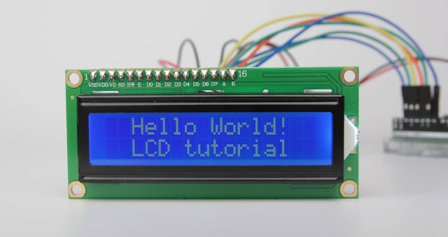
If the whole thing goes proper, you should see something like this on the show.

Code Explanation:
The caricature starts by way of together with LiquidCrystal library. As cited in advance in this educational, the Arduino network has a library called LiquidCrystal that makes programming the LCD module less hard. You can explore extra about the library on Arduino’s authentic internet site.
// include the library code:
#include <LiquidCrystal.H>
Next we should create an LiquidCrystal object. This item makes use of 6 parameters and specifies which Arduino pins are connected to the LCD’s RS pin, Enable pin, and statistics pins: d4, d5, d6, and d7.
// Creates an LCD item. Parameters: (rs, enable, d4, d5, d6, d7)
LiquidCrystal lcd(12, 11, 5, 4, 3, 2);
Now that you have declared a LiquidCrystal item, you could access unique methods (aka capabilities) which are unique to the LCD.
In the ‘setup’ characteristic: we are able to use two capabilities: The first feature is start() . This is used to specify the scale of the show i.E. How many columns and rows the display has. If you are the use of sixteen×2 person LCD, skip the parameters 16 & 2; If you are the usage of 20×four LCD, skip the parameters 20 & 4. You were given the point!
The 2d feature is apparent() .This clears the LCD display screen and movements the cursor to the higher left corner.
// installation the LCD's range of columns and rows:
lcd.begin(16, 2);
// Clears the LCD display
lcd.Clear();
In the ‘loop’ feature: we are able to use the print() characteristic which shows the message that we see on the first line of the screen.
// Print a message to the LCD.
lcd.Print(" Hello world!");
Following that we are able to set the cursor function to 2nd row, via calling feature setCursor() The cursor function specifies the region wherein you need the new text to be displayed on the LCD. The upper left nook is taken into consideration col=zero, row=0
cd.SetCursor(0, 1);
// Print a message to the LCD.
lcd.Print(" LCD Tutorial");
No comments:
Post a Comment